
leave a message
If you are interested in our products and want to know more details,please leave a message here,we will reply you as soon as we can.


How To Select an RFID Antenna
An RFID antenna is a necessary part of any RFID system. Unless the antenna is embedded into a reader, you will have to select and purchase the right antenna for your application. And there are a lot of options to select from.
Frequency– this will depend on your tags – choose between LF, HF, UHF or Microwave frequency.
Frequency Region– this will depend on country of operation and will affect only the UHF frequency. As you know, due to regulations, the frequency bands for UHF RFID slightly differ for US, Europe and other regions. Most UHF antennas are specified as globaland they are tuned for operation between 860 to 960 MHz. You can also find antennas that are specifically tuned for each region, which slightly improves their performance in the particular region. For instance, 865 - 868 MHz antenna will perform better when deployed in Europe than a global antenna, although this may not be distinguishable in most applications. Global antenna will work well for most applications; however, you can choose region-specific antenna for difficult deployments (long read ranges, RF challenging environment) or where global is not available.
Read range and size– smaller antennas within the same frequency will have shorter read range and vice versa. The antennas with the shortest read range for UHF technology will be Near Field Antenna, that utilize near field as opposed to far field as regular UHF antennas. These are often used for item tracking and where short ranges are required for item singulation and/or security purposes.
Profile width– if you are short on space or for esthetic reasons, you may need to look for low profile antennas that have a side connector or a side pigtail.
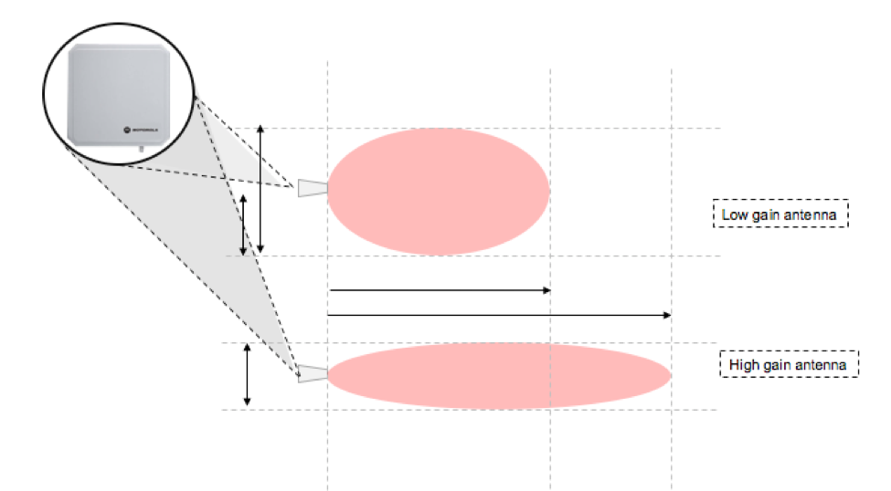
Gain– gain affects read range and beamwidth. Antennas with higher gain will have longer read range but narrower beam. Antennas with lower gain will have shorter read range and wider beam width. Select antenna gain based on the shape of your interrogation zone and coverage needs. Most common gain is 6dBi but you can find antenna with 1 dBi (low gain) and also with 11 dBi (high gain).
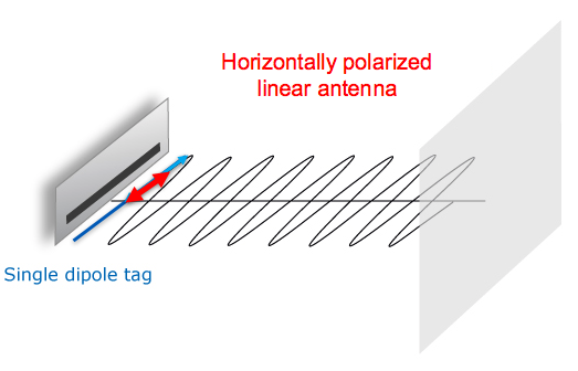
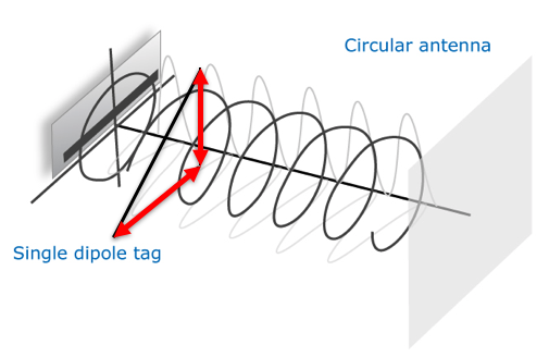
Polarization– you can select between circular and linear polarization. Circularly polarized antennas will have shorter read range but will be less orientation sensitive. You can select between right hand circularly polarized antennas (RHCP) or left hand circularly polarized antenna (LHCP). Sometimes you can see dual circularly polarized antennas that have both left hand and right hand polarization. Linearly polarized antennas will provide longer read range and more focused beam but will read only tags that have antennas parallel to the plane of wave. If your tag orientation is not fixed, especially when using single dipole tag antennas (which are most common), you should select a circularly polarized antenna.
VSWR– voltage standing wave ratio or also called return loss - Due to mismatches in impedance within the connector, some of the signal is reflected. The ratio of the input to the reflected signal is called the Voltage Standing Wave Ratio (VSWR). This ratio can also be measured in dB, and expressed as Return Loss. The VSWR signifies antenna design efficiency and the lower the VSWR the smaller the return loss and the better the antenna (ideal VSWR is 1:1).
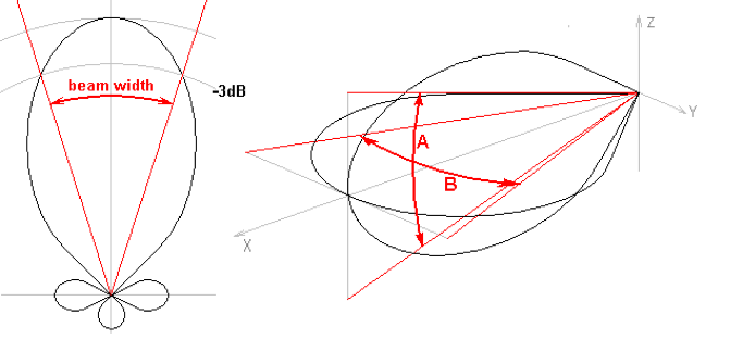
Axial Ratio- The axial ratio is the ratio of orthogonal components of an E-field. A circularly polarized field is made up of two orthogonal E-field components of equal amplitude, which are 90 degrees out of phase. Because these components are of equal magnitude, the axial ratio is 1 or 0 dB. Axial ratios are often specified for circularly polarized antennas. The axial ratio tends to degrade away from the main beam of an antenna, therefore, in the spec sheet for an antenna, you can sometimes see information such as: “Axial Ratio: <3 dB for +-30 degrees from the main beam”. This indicates that the deviation from circular polarization is less than 3 dB over the specified angular range.
Beam Width– select elevation beam width (vertical, up and down) and azimuth beam width (horizontal, left to right) based on the desired coverage of an interrogation zone. Wider beamwidth antennas will provide wider coverage without the need for additional antennas, however, the read range may be shorter (which is often desired as not to read tags outside the portal or door).
(The above content and pictures are reproduced from RFID4U Store)
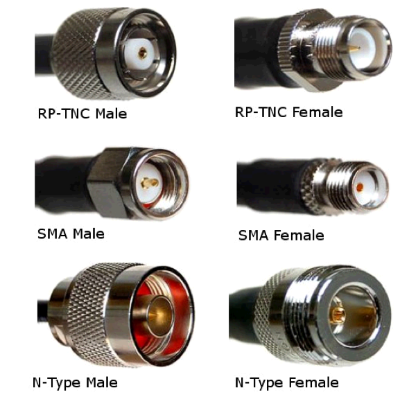
Antenna Connectors –there are several common types of connectors that are used with RFID antennas. They can be male or female and be regular or reverse polarity. Each manufacturer prefers certain connectors. In general, the connectors have no effect on performance, some are smaller and less bulky and therefore good for tight spaces or easier to hide and work better with thin cables. On the other hand, larger and bulkier connectors are sturdier and work with thicker cables and in harsher environments. You must know what connector your antenna has as well as your reader, so that you can purchase a cable that will pair with these. These connectors are most common: N-type, RP-TNC and SMA (the least bulky). Don't forget that youmust pair female and male connectors.
Front to Back Ratio – this ratio indicates the ratio of forward and backward signal transmission. Most if not all antennas radiate also to the back of the main beam, which is often due to the signal bending from the main beam. You want this ratio to be as large as possible unless you plan to utilize also the back beam (this is not usual).
Environmental Protection and Ruggedness – select an antenna with a suitable IP rating and made of materials that will survive the environment it will be installed in. Most antennas are enclosed in hard plastic, but there are also all metal antennas (suitable for very harsh environments or where they will suffer impact) or antennas encased in rubber (for mounting on the ground).
Antenna Selection Criteria Review
- Frequency – this will depend on your tags – choose between LF, HF, UHF or Microwave frequency.
- Frequency Region – Global, USA, EU, country specific – use global or per region
- Read range and size – smaller antennas within the same frequency will have shorter read range and vice versa.
- Profile width – if you are short on space or for esthetic reasons, you may need to look for low profile antennas that have a side connector or a side pigtail.
- Gain – gain affects read range and beamwidth. Antennas with higher gain will have longer read range but narrower beam. Antennas with lower gain will have shorter read range and wider beam width.
- Polarization – Circular, Dual Circular, or Linear.
- VSWR – look for VSWR as close to 1:1 as possible.
- Axial Ratio – look for as close to 1 or 0 dB as possible.
- Beam Width – based on your application and need for coverage.
- Antenna Connectors –N-type, RP-TNC and SMA. Consider your space and mounting. Some are bulkier than others, SMA is the smallest.
- Front to Back Ratio – You want this ratio to be as large as possible unless you plan to utilize also the back beam (this is not usual).
- Environmental Protection and Ruggedness – select an antenna with a suitable IP rating and made of materials that will survive the environment it will be installed in.

Detailed information and PDF

Support email contact.

Professional technical guidance.

Support email contact.


LINK

Youtube

leave a message
Scan to Wechat/Whatsapp :


 IPv6 Network Supported